3 SW'z Blue
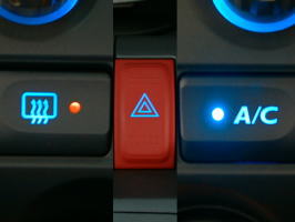 |
The illuminations of Hazard SW, Air Conditioner SW, Rear Defrostar SW change into blue LED .
In matching the color of these switches to it because illuminations around OE audio has already been changed to blue .
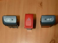 |
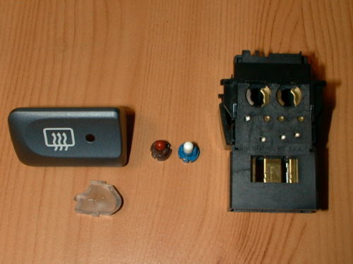
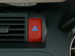
Hazard SW, Air Conditioner SW, Rear Defrostar SW who became the victim of this DIY . |
- Built-in
| Hazard Switch | |
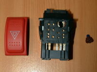 |
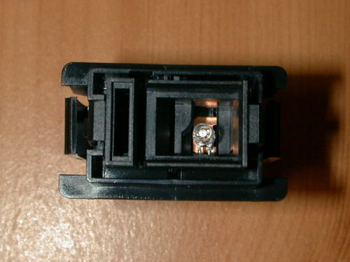
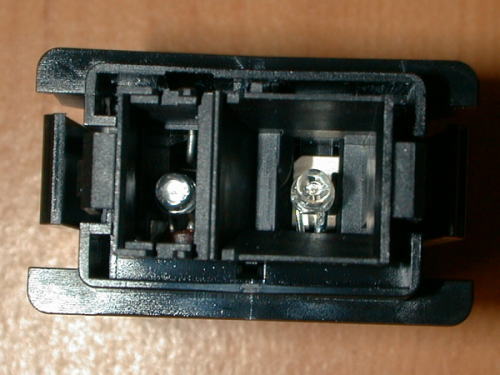
There is one electric bulb of about 3mm in the hazard switch . |
 |
A foundation and an electric bulb are disassembled . Since the leg of an electric bulb is only twisted around the foundation, it comes loose simply . This bulb might possibly not be a Hazard SW bulb . |
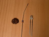 |
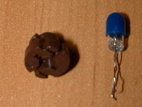
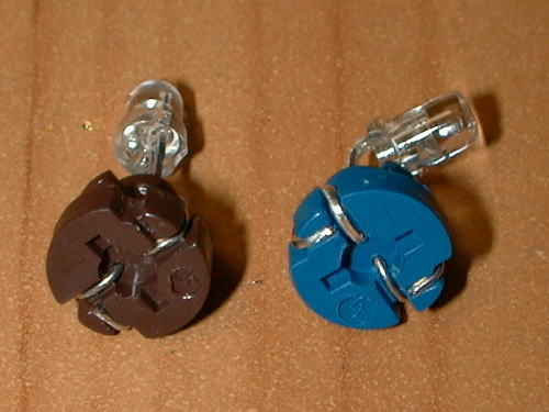
Ø3 Blue LED and 10mA CRD (Current Regulative Diode) . Just size of an electric bulb by Ø3 LED . |
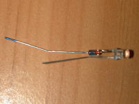 |
Because even the projection point was close-in, the evil ways
technique for flattening the head of LED this time was used . Reference "MIRROR/AUTO
Character Blue" . CRD is soldered with the cathode side of
LED (minus side) . You may connect CRD with the anode side (plus
side) . CRD has an electric polarity as well as LED . It is necessary
to note the direction . However, it's soldering to disregard specifications
of LED . |
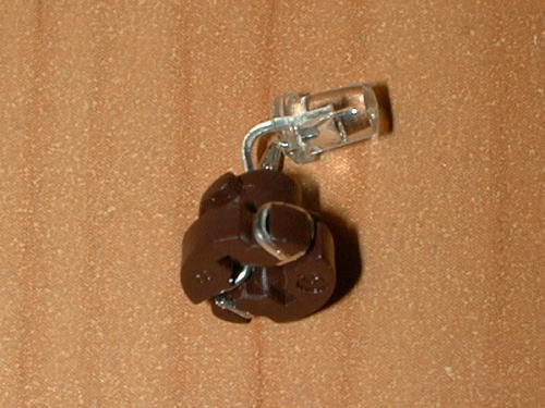 |
It inserts in a socket and a leg is twisted like an electric bulb
. It's a bend here to disregard the disclaimer of Lead-Forming completely
.(^-^) |
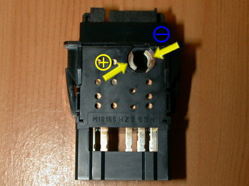 |
The socket that installed LED according to the polarity of the switch main body installs in the loading slot . It does not break, Only it doesn't light even if +/- is opposite . |
 |
After installed a socket, the head of LED is fine-tuned to turn to the projection point of pictograph and completion . |
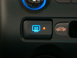
| Rear Defrostar Switch | |
 |
There are 2 bulbs in rear defrostar switch . For illumination of defrostar pictograph and Mark lamp at defroster ON . |
 |
The defrostar ON mark lamp used Orange LED . |
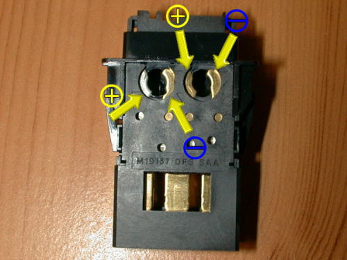 |
It's the +/- polarity of a switch main body . |
 |
It fine-tunes it for after here screws in . The mark lamp side in heat ray ON has a hard time a little to adjust the direction because space is narrow . |
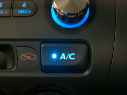
| Air Conditioner Switch | |
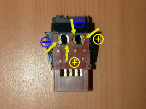 |
The +/- polarity of the Air-Con switch becomes it opposite to the rear defroster switch. 10mA CRD is used because it is the same as the defroster mark
lamp and clear acrylic fiber though the mark lamp side of air conditioner
ON is blue LED. The installation etc. are the same as the rear defrostar switch . |
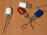 |
Dismissal cherry boy bulbs. 0.56W electric bulb . |
 |
 |
 |
 |
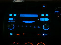
It has been gradually unified by having exchanged illumination of each switch for blue LED .
The remainder will be cool summer specification completely, if illumination of the circumference of an air-conditioner is changed blue .
Btw, because this one lamp is 0.56W, it is 2.8W every 5 pieces in total .
It became the power consumption of 0.78W, about 1/3.5 by exchanging these for LED .
![]()
|
|
|