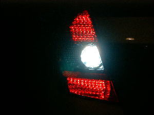
Full LED Tail-Light Specification
 |
( NOTE )
|
The construction
of this DIY is April, 2002.
|
Completes an
English translation in December, 2005.
|
It's strong of the impact that can be recognized from the outside at one-shot view ,
and I made it from probably Electric vehicle FIT/JAZZ in the future having equipped with such a tail-light .When making the Front-Winkers LED were ended, I vaguely thought it to be might rear next .
but, I never thought that take a cost very much ...
Many a little makes a mickle .
It's DIY that can be actually felt that the price of LED is still high . (^-^)<Attention>
This DIY adds the hand to an important indication light .
Therefore, Not only oneself but also the third person might be involved in the accident .
The validation of an expert is also necessary whether it's at least in the state that can be confirmed enough from the range where there is a description in the car inspection when this DIY is done .
| Materials |
|
||||||||||||
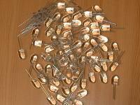 |
10mA CRD ( Current Regulative Diode ) . Additionally, I use Yellow color LED this
time because it was Orange near Red though I made the Front Winkers
with Orange color LED before . |
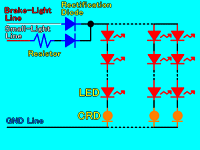
There are 3 kinds of main methods of lighting two or more LED with the car .
1: Resistors
2: Current Regulative Diode (CRD)
3: 3 Terminal RegulatorResistor is used to lower up to the rated voltage of LED .
CRD is used to throw the current only by the rated current of LED .
3 Terminal Regulator is used to secure a steady voltage.There is a method of individually using of each, and is a method of the combination using of each too .
In an individual usage,
It's " Resistor specification" that the cost is the cheapest .
It's " Current Regulative Diode (CRD) specification" that the cost is the highest .
It's " Current Regulative Diode (CRD) specification" and " 3 Terminal Regulator specification" to be able to secure the steadiest light .
It's " Resistor specification" and " Current Regulative Diode (CRD) specification" that use is the easiest .
It's " 3 Terminal Regulator specification" not to use easily most .The battery voltage is higher than that of 12V because it is charged (Fit is about 14.4V) when the alternator operates .
but, The battery voltage is considerably unstable when the electrical equipments such as air conditioners and the Headlight and wipers etc are movable .
It's not a steady voltage at all .
When use LED is 1 or 2 pieces and is little, light seems to be steady .
but, When LED is arranged in large quantities and used, the flicker is understood further more by the voltage change of the battery ." Resistor specification" is influenced directly by the change of the voltage .
This is because the number of LED used from the maximum value of the battery voltage is calculated and it calculated the Resistor .
And, In addition, It's because of use without stabilizing an unstable power supply .
Resistors changes fundamentally by the change of the voltage in this method, too .
When a voltage any more has been generated in 12V calculation, LED will be driven more than the rated voltage of the LED .
Moreover, if it's the case when do not Over-Drive, because the Resistor with large of Resistor value will be used from the reserve strength of the voltage, brightness (OOOO mcd) when the rated voltage of LED is driven cannot be obtained .
40mA of twice as many abbreviation as 20mA of rated current will flow only by voltage rising by 0.2V from rated voltage . (General Red color family LED is 50mA in the maximum current)
The Red color LED family has the character to be easy to pass current from Blue, White, etc .
It's not good to exceed the rated voltage and the rated current if it thinks about the longevity of LED .
but, if you use it for the place (Interior etc.) without the necessity of brightness severely, the Resistors are advantageous in the cost and easiness to use overwhelmingly .Rated current value of use LED in case of " Current Regulative Diode (CRD) specification",
For example, if it is 20mA, the current of 20mA or more doesn't flow because it's 20mA in the connected in parallel with 10mACRD . (There is an error margin.)
Therefore, because the current flows only by 20mA even when two or more LED is used by the series, or even when you use one LED, you may not calculate about voltage or current .
When Resistor is used, the Resistor value calculation is necessary in Ohm's law .
but it might be easy to use CRD further because the calculation is unnecessary .
Moreover, when the voltage of 3.5V(For 10mACRD) or more(Until 50V) hangs to CRD, the output current is constant .
But, it influences the voltage change for 3.5V or less .
(About CRD details on SEMITEC website )
So, calculating the voltage value of LED and CRD so that the battery voltage may become 12V or less from MAX(About 14.4V) and using it are steady the current .For " 3 Terminal Regulator specification", In the car usually with a regulator of 12V output . (There is an exception)
In that case, even if the input voltage is the lowest, 14V or more is necessary .
A steady 12V is output even if there is considerable voltage change (11V-35V) .
butr, when the input voltage drops below 12V, it's cannot also output 12V .
So, the voltage is unstable at 12V or less .
and the regulator generates heat, so it's necessary to install the heat sink to radiate heat .
When parts are put in the limited space, the taking turning might be serious .
Electric knowledge is also necessary because it doesn't use it with Reguretar alone though the cost is cheap next the Resistor .
( It's composed of several parts. like a Stabilizing Supply)< Various and reference prices at DenDenTown in JPN >
Resistor : 5.00 Yen/piece (Necessary in each systems or root)
CRD : 120.00 Yen/piece (Necessary in each systems)
3 Terminal Regulator : 300.00 Yen/piece + ƒ¿ (Necessary only for root)Though I wrote some difficult things,
A difficult connection method and electric knowledge also almost unnecessary,
In the method of obtaining a stable light,
Although cost increases, " Current Regulative Diode (CRD)" of a standard method is used .CRD is OK even if it connects it with either Plus(+) side or Minus(-) side of LED .
| Manufacture |
|
|
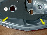 |
Disassemble a Tail-light . There is Tapping-Screw to have special shape in two places of
the arrow . |
|
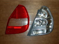 |
The hot water is put in Taillight ASSY in the bathroom, wrenched it open in the Minus-Driver after it leaves it for several minutes . Once, I have cracked the Taillight of just purchase as for least
. |
|
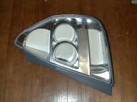 |
The paper pattern is made for cutting out the Universal Electric Board . It's necessary to adjust the installation angle especially the
Brake-Light . |
|
|
||
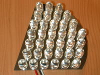 |
This is an Upper Brake-light . The specular cutting sticker is pasted to the Universal Electric
Board . Ratings 1.9V 20mA Red Ø10 LED : 36 pieces |
|
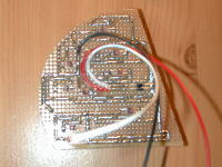 |
Series connection of parallel 10mA CRD to 4 pieces LED . <One system> The Brake-light limit the current by Resistor at the time of Small-light
. |
|
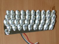 |
This is a lower side Brake-light . Ratings 1.9V 20mA Red Ø10 LED : 40 pieces This Full LED specification does "The Lower side lighting" of standard fit DIY of the Mr. Spoon design though this lower side is not used in the normal Fit (Before 04 JDM Models). |
|
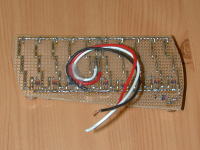 |
Same as the upper Brake-light . <One system> TOTAL : 10 system specification . |
|
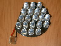 |
This is a Back Light . Ratings 3.5V 20mA White Ø10 LED : 20 pieces |
|
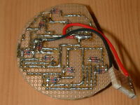 |
Series connection of parallel 10mA CRD to 2 pieces LED . <One system> TOTAL : 10 system specification . |
|
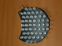 |
This is a Winker ( Blinker/Turn signal ) . The Winker part should not be a specular cutting sticker . Ratings 1.9V 20mA Yellow Ø5 LED : 51 pieces |
|
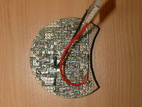 |
Series connection of parallel 10mA CRD to 4 pieces LED . Though I want to have done to 52 pieces by equalizing the voltage,
The beauty of arrangement is also necessary because LED of Winker
part is fully exposed from the outside . (^o^) |
|
|
||
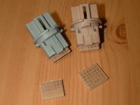 |
A plug is created by the Universal Electric Board so that it can
insert in the socket of a normal electric bulb. If each taillight ASSY exchanges by opening pulling out about the plug, it is possible to return it at once normally . |
|
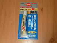 |
A strong Elasticity adhesive for
shock was used to install in the LED board into Taillight ASSY
. It's heatproof, water-proof, and shockproof . |
|
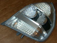 |
The cutting sticker of the carbon design pasted to the side of the Taillight . As for an Electric vehicle Fit/Jazz, it's likely to be equipped with such a Taillight . |
|
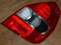 |
The final lighting check is done, clean the inside dust, and installed the lens . Alhough the adhesive-seal on the market was prepared by way of
precaution, the adhesive-seal that adhered to Taillight ASSY was
able to be recycled as it was . |
|
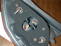 |
Here is bottom view of Taillight ASSY . It's adjustable the brightness at the time of an up-and-down Small-light
by two volumes at the center . If it did not actually confirm how much brightness was good by
eyes in outdoor, resistor value was not decided to me . |
|
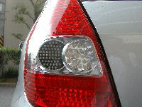 |
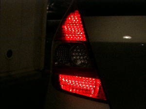
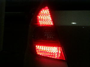
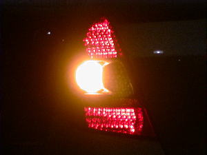
Completion finally . There is considerably an impact . It's super-love for me . (^o^) |
|
|
Small Light |
Brake Light |
|
Winker (Blinker/Turn signal) |
Back Light |
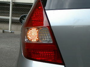 |
Grain of LED is seen when approaching . But, 3 pieces are turned off at the same time as breaking by even
1 piece among these . ( 3 half years have already been passing.) |
The manufacturer seems to be making only 1000 LED a month used for winker part LED used this time . (At present 25 May 2002, New item TLYH20TP)
The making period is about 1 month .
I spent considerable money due to making for trial purposes, the failure, making for trial purposes, and the failure .
But, because it was a compilation of DIY for me, this completion is big satisfactory .By the way,
Power consumption sum total 188W (Include the lower side lighting) of the normal electric bulb of a Taillight part turned into 20.16W by Full LED-ization .
(It's LED ratings of right and left Taillight total to simplicity. )* The measure DIY against a high-flasher of the Winker(Blinker) accompanying LED-izing is to [ "Blink Interval Adjustable Flasher Relay" ] .
(It has not translated into English yet.)
| Extra. | |||||||||||||||||
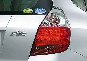 From 05 MODEL HONDA Fit LED Taillight . . |
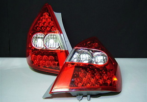 Aftermarket parts . First model design type LED Taillight . |
||||||||||||||||
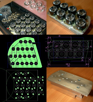 |
|
![]()
